A full breadboard tutorial will be released soon. The following is a copy of the lab instructions from EEEN20020 and EEEN20050 respectively. All rights reserved.
A reusable board that allows building and connecting small electronic components without soldering. It provides a grid of holes with spring-loaded metal contacts. In the main part of the breadboard, these contacts are connected together in groups of six along the rows - see the figure below for the full connection diagram.
Insert the wire ends of your resistor into holes in the main part of the breadboard, making sure that the two ends are in different contact groups, so that they are not connected together.
The diagram shows the electrical connections in the breadboard. The small circles represent the holes with spring-loaded contacts. The large circles represent the coloured 4mm sockets. The lines indicate the electrical connections. Most of the contacts are connected in groups of six, but note the connectivity of the long rows near the top and bottom of the breadboard; we normally use these as power and ground rails.
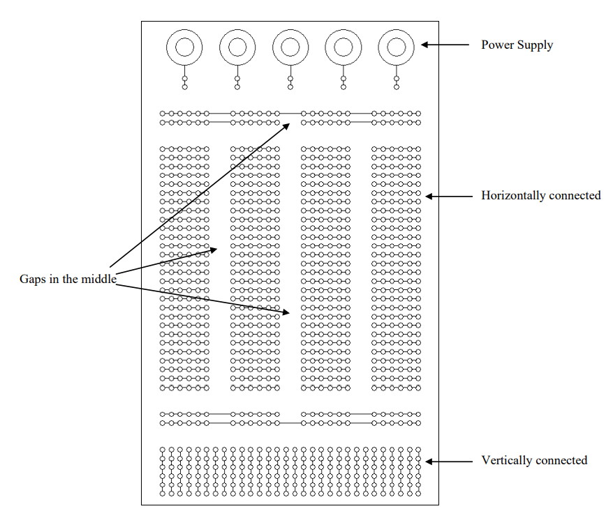
Figure: Breadboard layout

Figure: Electrical components layout on breadboard