A full tutorial on using a power supply will be released soon. The following is a copy of the lab instructions from EEEN20020. All rights reserved.
To force some current through your resistor, you need something which can produce a voltage (potential difference) between its terminals. In this case, we will use the dual output power supply shown:
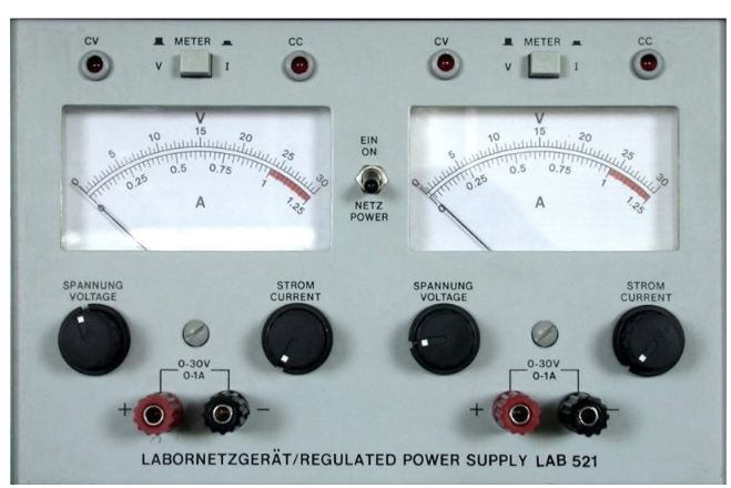
Figure: Lab power supply
This comprises two separate power supplies in one box - you can use either half of it. Each power supply has two controls, marked “Voltage” and “Current”, and two terminals or connection points - these are the 4 mm sockets, coloured red and black and marked “+” and “-“ respectively.
The voltage control sets the voltage which should appear between the terminals of the power supply - with the reference direction positive on the red socket, negative on the black socket. It is adjustable from 0 to 30 V.
The current control is for safety purposes. It sets the maximum current which the power supply will provide. It is adjustable from 0 to 1 A. It is often useful to set this to a low value, to limit the current which could flow, and the damage which could occur, if you have not wired your circuit correctly!
The meter above the controls can be switched to show either the voltage between the power supply terminals, or the current flowing into the circuit that is connected to the power supply. However, it does not have very high resolution and therefore is used only a guide - the other meters in the laboratory will give more precise results.