Task4 – Potentiometer
📝 Task 4
In TinkerCAD, program the servo to read a potentiometer and set the angle accordingly.
Brief
Until now, we’ve been giving the servo fixed angles in code.
That’s cool, but real-world devices - joysticks, dials, sensors - send variable inputs that continuously change.
In this task, you’ll use a potentiometer (a variable resistor) as an analog input to control the servo’s angle in real time.
Spin the knob → servo moves. Simple as that.
Objectives
- Learn to read analog values with
analogRead() - Map sensor readings to servo movement
Equipment
- TinkerCAD account
- x1 Arduino Uno (virtual)
- x1 Servo (9g or similar)
- x1 Potentiometer
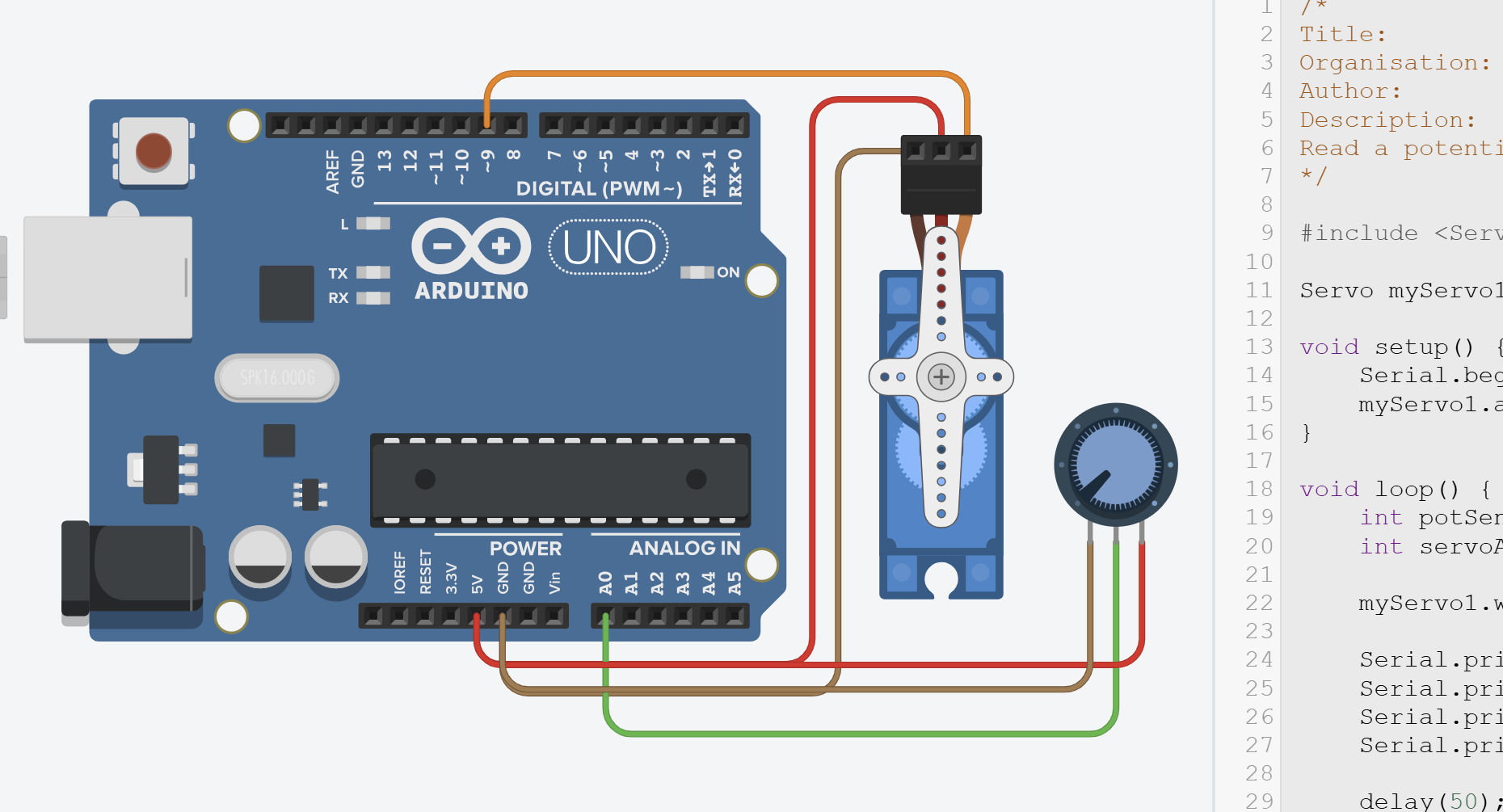
Step 1 – Circuit Setup
Reuse your design from Task 1.
Add a potentiometer and wire it so:
- Left pin → GND
- Middle pin → A0
- Right pin → 5V (VCC)
Unlike digital I/O pins (D0–D13), analog pins (A0–A5) can only take inputs.
Their advantage is that they include a built-in Analogue-to-Digital Converter (ADC), meaning they can sense voltages from 0–5 V and return a corresponding digital value from 0–1023 - kind of like a mini-multimeter inside the chip!
Step 2 – Programming the Servo with Potentiometer
Understanding analogRead()
The potentiometer acts as a voltage divider: as you turn the knob, the voltage on the middle pin varies smoothly from 0V to 5V.
int potSensorValue = analogRead(A0);
The Arduino’s 10-bit Analog-to-Digital Convertor (ADC) converts that voltage into a number between 0 and 1023:
- 0 → 0 V (knob fully counter-clockwise)
- 512 → ≈ 2.5 V (middle position)
- 1023 → 5 V (fully clockwise)
Each step represents about 4.9mV (5V / 1023 ≈ 0.0049V).
About the AREF Pin
The AREF (Analog Reference) pin on the Arduino lets you change what voltage corresponds to the maximum
analogRead()value of 1023. By default, the reference is the board’s 5 V supply, meaning0V → 0and5V → 1023.However, you can improve accuracy for lower-voltage sensors by providing your own precise reference (for example, 3.3 V or 1.1 V) to the AREF pin and calling
analogReference(EXTERNAL);NEVER connect anything to AREF without setting
analogReference(EXTERNAL)first -otherwise, you could short the internal reference.
Mapping the Analog Input to Servo Range
The <Servo.h> library expects an angle between 0° and 180°, not a raw sensor value.
To link these scales, Arduino provides the map() function, which rescales one range to another:
map(value, fromLow, fromHigh, toLow, toHigh);
We can use it like this:
int servoAngle = map(potSensorValue, 0, 1023, 0, 180);
Now:
- when the knob is at 0 V → servoAngle = 0°
- halfway → ≈ 90°
- at 5 V → 180°
You can also get the actual voltage if you like:
float voltage = potSensorValue * (5.0 / 1023.0);But we’ll just use the raw integer for now.
Writing the Values to the Servo
Once we have our mapped angle, we can send it to the servo and (optionally) print the readings to the Serial Monitor:
myServo1.write(servoAngle);

Serial.print("Pot: ");
Serial.print(potSensorValue);
Serial.print(" | Angle: ");
Serial.println(servoAngle);
Full Code
/*
Title:          MakerLab2-Task4-Potentiometer
Organisation:   UCD ElecSoc – MakerLab
Author:         Joe Biju
Description:
Read a potentiometer and set servo angle based on the input.
*/

#include <Servo.h>

Servo myServo1; // create servo object

void setup() {
    Serial.begin(9600); // Optional – for debugging
    myServo1.attach(9, 500, 2500); // Servo signal pin
}

void loop() {
    int potSensorValue = analogRead(A0);                   // Read potentiometer (0–1023)
    int servoAngle = map(potSensorValue, 0, 1023, 0, 180); // Convert range

    myServo1.write(servoAngle);                         // Move servo to mapped angle

    Serial.print("Pot: ");                    // Optional serial output
    Serial.print(potSensorValue);
    Serial.print(" | Angle: ");
    Serial.println(servoAngle);

    delay(50); // Small delay for smoother movement
}
Step 3 - Run
Copy the code and run it on TinkerCAD.
Open the Serial Monitor to see the debug statements.
Step 4 – Modify and Explore
Try changing parameters such as for the map() function and see what new behaviours you can create.
Set the delay to 10ms. Set it to 100ms. How does the responsiveness of the servo change?